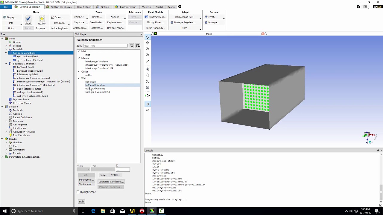
Applying boundary conditions in ANSYS is a critical step in setting up finite element analyses (FEA), computational fluid dynamics (CFD) simulations, and other engineering simulations. Boundary conditions define the interactions between the model and its environment, specifying how the model responds to external forces, constraints, thermal conditions, fluid flow conditions, and other physical phenomena. This comprehensive guide will provide a detailed walkthrough of the process for applying boundary conditions in ANSYS, covering different types of boundary conditions, methods for application, best practices, and troubleshooting tips.
Table of Contents
- Introduction to Boundary Conditions in ANSYS
- Types of Boundary Conditions
- Methods for Applying Boundary Conditions
- Best Practices for Applying Boundary Conditions
- Troubleshooting Boundary Condition Issues
- Conclusion
1. Introduction to Boundary Conditions in ANSYS
Boundary conditions in ANSYS define the constraints and loads applied to the model, ensuring that the simulation accurately represents real-world operating conditions. They play a crucial role in determining how the model behaves under different scenarios, influencing results such as stress distribution, temperature gradients, fluid flow patterns, and electromagnetic field interactions. Understanding and correctly applying boundary conditions are essential for obtaining reliable simulation results and making informed engineering decisions.
2. Types of Boundary Conditions
Structural Analysis
- Displacement Boundary Conditions:
- Specify fixed displacements or prescribed movements at certain points or surfaces.
- Example: Fixing a surface in a structural analysis to simulate a clamped boundary.
- Force or Load Boundary Conditions:
- Apply forces, pressures, or distributed loads to model external forces acting on the structure.
- Example: Applying a distributed load on a beam or applying pressure on a surface.
- Remote Displacement Boundary Conditions:
- Define displacements indirectly through remote points or reference surfaces.
- Example: Linking displacements of one part of the structure to another part via coupling conditions.
Thermal Analysis
- Temperature Boundary Conditions:
- Specify fixed temperatures or temperature gradients on surfaces or boundaries.
- Example: Applying a uniform temperature on a heat sink surface in a thermal analysis.
- Heat Flux Boundary Conditions:
- Define heat fluxes or heat sources applied to surfaces to simulate thermal loading.
- Example: Specifying a heat flux on an electronic component surface.
Fluid Dynamics (CFD)
- Velocity Boundary Conditions:
- Set inlet velocities, outlet pressures, or flow rates to simulate fluid flow behavior.
- Example: Applying a specified velocity profile at the inlet of a pipe.
- Pressure Boundary Conditions:
- Define static pressures or total pressures at inlet or outlet boundaries.
- Example: Specifying a pressure boundary condition at the outlet of a duct.
Electromagnetics
- Electric Potential Boundary Conditions:
- Set voltages or electric potentials on conductors or boundaries.
- Example: Applying a voltage difference between two electrodes.
- Magnetic Field Boundary Conditions:
- Define magnetic flux densities or currents applied to surfaces.
- Example: Specifying a magnetic flux density on a magnet surface.
3. Methods for Applying Boundary Conditions
- Workbench Environment:
- Launch ANSYS Workbench and create a new project for structural, thermal, fluid, or electromagnetic simulations.
- Navigate to the appropriate module (Mechanical, Fluent, Maxwell, etc.) based on the analysis type.
- Geometry Selection:
- Select the geometry component or parts where boundary conditions need to be applied.
- Use tree outlines in Workbench or graphical user interfaces (GUIs) in Mechanical, Fluent, or Maxwell to identify geometry parts.
- Boundary Condition Assignment:
- Use GUI menus to define boundary conditions specific to the simulation type (e.g., Mechanical, Thermal, Fluids, Electromagnetics).
- Apply conditions such as fixed displacements, loads, pressures, temperatures, velocities, or potentials to selected geometry faces or nodes.
- Load and Constraint Definition:
- Define loads (forces, pressures, heat fluxes) and constraints (displacements, temperatures, velocities) using input dialogs or command line interfaces.
- Specify numerical values, directions, distributions, and coordinate systems for boundary conditions as required by the simulation setup.
4. Best Practices for Applying Boundary Conditions
- Consistency and Completeness:
- Ensure all necessary boundary conditions are defined comprehensively for accurate simulation results.
- Verify consistency in units, scales, and definitions across all boundary conditions applied.
- Realism and Simulation Objectives:
- Align boundary conditions with realistic operational scenarios and engineering objectives.
- Consider transient conditions, dynamic loading, and environmental factors influencing boundary conditions.
- Verification and Validation:
- Validate boundary conditions against analytical solutions, experimental data, or physical observations.
- Conduct sensitivity analyses to assess the impact of boundary conditions on simulation outcomes.
- Documentation and Repeatability:
- Document boundary conditions clearly in simulation reports or project documentation.
- Ensure repeatability by saving simulation setups or using scripting for automated boundary condition assignment.
5. Troubleshooting Boundary Condition Issues
- Convergence and Solver Issues:
- Address convergence problems by adjusting boundary condition values, solver settings, or mesh refinement.
- Monitor solution convergence and stability throughout the simulation process.
- Inconsistencies in Results:
- Verify boundary conditions for consistency and correctness to resolve discrepancies in simulation results.
- Check for unintended constraints or loads that may affect simulation outcomes.
- Geometry and Mesh Quality:
- Ensure high-quality geometry and meshing to support accurate boundary condition application.
- Refine meshes in critical regions or use adaptive meshing techniques to improve solution accuracy.
6. Conclusion
Applying boundary conditions in ANSYS is a crucial aspect of preparing simulations across structural mechanics, thermal analyses, fluid dynamics, electromagnetics, and more. By following the methods, understanding different types of boundary conditions, and adhering to best practices outlined in this guide, engineers and analysts can effectively define and apply boundary conditions to accurately simulate real-world scenarios and predict system behavior. ANSYS’s versatile capabilities for boundary condition assignment, coupled with advanced simulation tools, empower users to optimize designs, solve complex engineering challenges, and make informed decisions with confidence and precision. Mastering boundary condition application enhances the reliability and efficiency of simulations, driving innovation and engineering excellence across diverse industries.