Mastering Data Acquisition with LabVIEW: A Comprehensive Guide
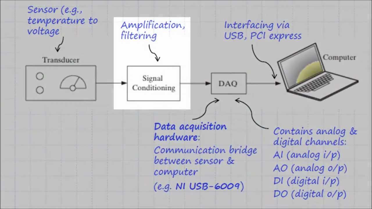
Introduction: LabVIEW, short for Laboratory Virtual Instrument Engineering Workbench, is a powerful graphical programming environment developed by National Instruments for data acquisition, instrument control, and […]