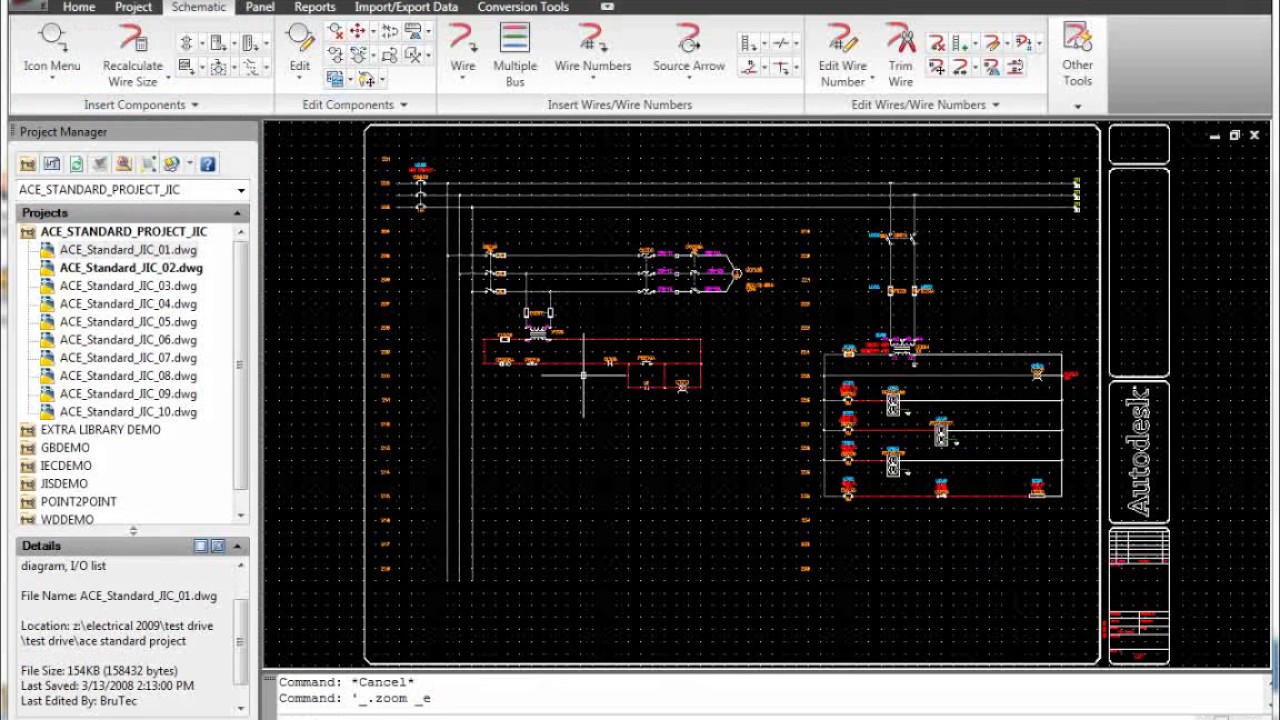
Creating and utilizing circuits in Autodesk Electrical is essential for designing efficient and reliable electrical systems. Circuits define the flow of electrical current and enable designers to visualize, analyze, and optimize electrical connections within schematic drawings. In this extensive guide, we will delve into the intricacies of creating and using circuits in Autodesk Electrical, providing detailed instructions, best practices, and expert tips to help you master this fundamental aspect of electrical design.
Understanding the Significance of Circuits
Circuits serve as the backbone of electrical systems, facilitating the flow of current and enabling the operation of various devices and components. The significance of circuits in electrical design encompasses several key aspects:
- Functionality: Circuits define the functional relationships between components within an electrical system, ensuring that power is delivered to the intended destinations.
- Safety and Protection: Properly configured circuits incorporate protective devices such as fuses, circuit breakers, and overcurrent relays to safeguard against electrical faults and hazards.
- Efficiency and Optimization: Optimized circuit layouts minimize power losses, voltage drops, and electromagnetic interference, enhancing the efficiency and performance of electrical systems.
Creating Circuits in Autodesk Electrical
Now, let’s explore the step-by-step process of creating circuits within Autodesk Electrical:
Step 1: Access Circuit Creation Tools
- Circuit Builder: Navigate to the circuit builder tool within Autodesk Electrical to access the interface for creating circuits.
- Component Selection: Choose the components and devices that will comprise the circuit, including power sources, loads, switches, and protective devices.
Step 2: Define Circuit Topology
- Connection Points: Define connection points or terminals on each component to establish the logical and physical connections between devices.
- Wiring Paths: Determine the wiring paths and routes that will connect the components within the circuit, considering factors such as wire gauge, voltage rating, and current capacity.
Step 3: Wire Routing and Connection
- Wire Routing Tools: Utilize wire routing tools to route wires and cables between components, ensuring proper separation, bundling, and routing to minimize interference and maintain neatness.
- Connection Validation: Validate connections between components to ensure continuity, polarity, and proper termination of conductors.
Step 4: Customize Circuit Properties
- Circuit Properties Editor: Access the circuit properties editor to define circuit parameters such as voltage level, current rating, phase configuration, and frequency.
- Naming and Labeling: Assign descriptive names and labels to circuits to facilitate identification, organization, and documentation within schematic drawings.
Utilizing Circuits in Autodesk Electrical
After creating circuits, it’s crucial to leverage them effectively within schematic drawings:
Circuit Analysis and Simulation
- Voltage Drop Analysis: Perform voltage drop analysis to assess the voltage levels across different segments of the circuit and identify potential areas of concern.
- Load Balancing: Optimize circuit configurations to balance loads evenly across phases and ensure efficient utilization of electrical resources.
Troubleshooting and Maintenance
- Fault Detection: Utilize circuit diagrams to troubleshoot electrical faults and identify the root causes of circuit interruptions, overloads, or short circuits.
- Maintenance Planning: Incorporate circuit information into maintenance plans and documentation to facilitate preventive maintenance activities and minimize downtime.
Documentation and Reporting
- Bill of Materials (BOM): Generate a bill of materials (BOM) directly from circuit diagrams to document the components and quantities required for circuit assembly.
- Drawing Output: Export circuit diagrams as standard CAD drawings or PDF files for documentation, collaboration, and presentation purposes.
Best Practices for Circuit Creation and Utilization
To optimize the process of circuit creation and utilization in Autodesk Electrical, consider the following best practices:
Planning and Design
- Systematic Approach: Plan circuit layouts systematically, considering factors such as load requirements, voltage levels, and safety considerations.
- Modular Design: Adopt a modular design approach to create reusable circuit templates and standardize circuit configurations across projects.
Accuracy and Validation
- Validation Checks: Perform validation checks on circuits to ensure compliance with design specifications, regulatory requirements, and industry standards.
- Peer Review: Conduct peer reviews of circuit diagrams to gather feedback, identify errors, and improve the accuracy and reliability of circuit designs.
Documentation and Collaboration
- Comprehensive Documentation: Document circuit designs comprehensively, including detailed annotations, labels, and component specifications.
- Collaborative Environment: Foster collaboration among team members, engineers, and stakeholders to share insights, exchange ideas, and refine circuit designs collaboratively.
Conclusion
Mastering circuit creation and utilization in Autodesk Electrical is essential for designing efficient, reliable, and compliant electrical systems. By following the steps outlined in this guide and adhering to best practices, you can create circuits that accurately represent the functional relationships between components, optimize system performance, and enhance safety and reliability. Whether you’re designing circuits for industrial automation, building management systems, or power distribution networks, proficiency in circuit creation and utilization will empower you to deliver superior results and exceed client expectations.