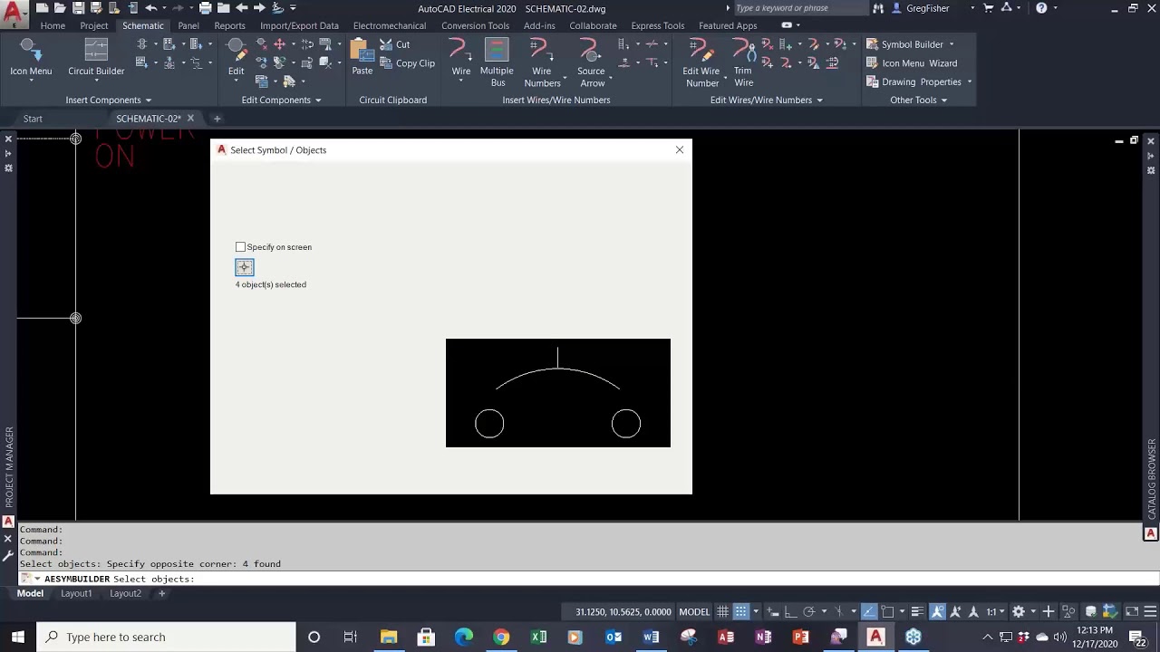
Custom component symbols play a vital role in electrical design, enabling designers to represent specialized or unique devices accurately within schematic drawings. Autodesk Electrical provides powerful tools for creating custom component symbols, allowing designers to tailor their symbol library to meet specific project requirements. In this extensive guide, we will explore the intricate process of creating custom component symbols in Autodesk Electrical, providing detailed instructions, best practices, and expert tips to help you master this essential aspect of electrical design.
Understanding the Importance of Custom Component Symbols
Custom component symbols serve several crucial functions within electrical schematic drawings:
- Accurate Representation: Custom symbols enable designers to accurately represent specialized or proprietary devices that are not available in standard component libraries.
- Standardization: Creating custom symbols ensures standardization across projects, enabling consistency and clarity in schematic diagrams.
- Efficiency and Productivity: Tailoring the symbol library to include custom symbols minimizes the need for manual modifications or annotations, streamlining the design process and enhancing productivity.
Creating Custom Component Symbols in Autodesk Electrical
Now, let’s delve into the step-by-step process of creating custom component symbols within Autodesk Electrical:
Step 1: Access Symbol Builder
- Symbol Builder: Navigate to the symbol builder tool within Autodesk Electrical to access the interface for creating custom component symbols.
- Template Selection: Choose a suitable template or starting point for the custom symbol based on the type and complexity of the device.
Step 2: Design Symbol Geometry
- Drawing Tools: Utilize drawing tools such as lines, arcs, circles, and polygons to create the geometric shapes comprising the custom symbol.
- Accuracy and Precision: Ensure that symbol geometry accurately represents the physical attributes and functional characteristics of the device.
Step 3: Add Graphic Elements
- Graphic Elements: Incorporate graphic elements such as labels, text, icons, and graphical representations of device features or indicators.
- Alignment and Consistency: Maintain alignment and consistency in the placement and styling of graphic elements to enhance readability and visual appeal.
Step 4: Define Connection Points
- Connection Points: Define connection points within the custom symbol to indicate the locations where wires or conductors will be attached.
- Alignment and Orientation: Position connection points strategically to facilitate logical and intuitive wiring configurations within schematic drawings.
Step 5: Assign Attributes and Properties
- Attribute Editor: Access the attribute editor to assign properties such as component type, function, voltage rating, and manufacturer part number.
- Symbol Properties: Define symbol properties such as size, rotation, visibility, and layer assignment to ensure compatibility with schematic drawings.
Best Practices for Creating Custom Component Symbols
To optimize the process of creating custom component symbols in Autodesk Electrical, consider the following best practices:
Research and Reference
- Device Specifications: Gather detailed specifications, datasheets, and reference materials for the device being represented to ensure accurate symbol creation.
- Industry Standards: Refer to industry standards, guidelines, and best practices for symbol design and representation to maintain compatibility and compliance.
Collaboration and Feedback
- Team Collaboration: Collaborate with engineers, technicians, and stakeholders to gather input, feedback, and insights during the symbol creation process.
- Iterative Design: Iterate on symbol designs based on feedback and review cycles to refine and improve symbol accuracy, clarity, and functionality.
Documentation and Organization
- Documentation: Document symbol creation processes, guidelines, and standards to facilitate consistency, repeatability, and knowledge transfer within the design team.
- Library Management: Organize custom symbols within a centralized library or database to ensure easy access, retrieval, and sharing across projects.
Conclusion
Creating custom component symbols in Autodesk Electrical is a meticulous yet rewarding process that requires creativity, technical proficiency, and attention to detail. By following the steps outlined in this guide and adhering to best practices, you can create custom symbols that accurately represent specialized devices, enhance schematic clarity and readability, and streamline the electrical design process. Whether you’re designing control systems, automation circuits, or power distribution networks, proficiency in creating custom component symbols will empower you to deliver superior results and exceed client expectations.