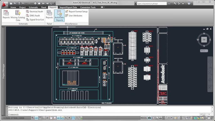
Designing a panel layout is a critical aspect of electrical engineering, ensuring that components are arranged efficiently, safely, and aesthetically within control panels. Autodesk Electrical provides powerful tools to streamline the panel layout process, enabling designers to create professional-grade layouts with ease. In this extensive guide, we will delve into the intricacies of creating a panel layout in Autodesk Electrical, providing step-by-step instructions, best practices, and expert tips to help you master this essential aspect of electrical design.
Understanding the Importance of Panel Layouts
Panel layouts serve as the physical manifestation of electrical schematics, translating design concepts into tangible configurations within control panels. The importance of panel layouts lies in several key areas:
- Efficiency and Accessibility: Well-designed panel layouts optimize space utilization and component placement, ensuring that components are easily accessible for installation, maintenance, and troubleshooting.
- Safety and Compliance: Properly arranged components minimize the risk of electrical hazards and ensure compliance with safety standards and regulations, protecting both personnel and equipment.
- Aesthetics and Professionalism: A visually appealing panel layout reflects positively on the professionalism and attention to detail of the designer, enhancing the overall quality of the electrical installation.
Creating a Panel Layout in Autodesk Electrical
Now, let’s explore the process of creating a panel layout within Autodesk Electrical:
Step 1: Define Panel Specifications
- Panel Size and Configuration: Determine the dimensions and configuration of the control panel based on project requirements, equipment specifications, and space constraints.
- Component Placement: Identify the placement of major components such as power supplies, circuit breakers, controllers, and terminal blocks within the panel.
Step 2: Access Panel Layout Tools
- Panel Layout Workspace: Navigate to the panel layout workspace within Autodesk Electrical to access panel layout tools and options.
- Insert Components: Use the component insertion tools to add predefined panel components such as enclosures, mounting rails, and DIN rails to the panel layout.
Step 3: Arrange Components
- Drag-and-Drop: Drag and drop components from the component library onto the panel layout canvas, arranging them according to the defined specifications.
- Alignment and Spacing: Use alignment and spacing tools to ensure consistent placement and alignment of components within the panel.
Step 4: Route Wires and Cables
- Wire Routing Tools: Utilize wire routing tools to route wires and cables between components within the panel layout.
- Optimize Routing: Optimize wire routing to minimize clutter and ensure efficient use of space within the panel.
Customizing Panel Layouts in Autodesk Electrical
Autodesk Electrical offers a range of customization options to tailor panel layouts to specific project requirements:
Custom Component Creation
- Custom Symbols: Create custom symbols for unique components or devices not available in the standard component library.
- Symbol Editor: Use the symbol editor to design custom symbols with the desired appearance and functionality.
Visualization and Annotation
- 3D Visualization: Leverage Autodesk Electrical’s 3D visualization capabilities to view panel layouts in a three-dimensional space, providing a more realistic representation of the final installation.
- Annotations: Add annotations, labels, and callouts to panel layouts to provide additional information and clarify component functions or connections.
Project Documentation
- Bill of Materials (BOM): Generate a bill of materials (BOM) directly from the panel layout to document the components and quantities required for the panel assembly.
- Drawing Output: Export panel layouts as standard CAD drawings or PDF files for documentation and collaboration purposes.
Best Practices for Panel Layout Design
To optimize the design of panel layouts in Autodesk Electrical, consider the following best practices:
Safety and Compliance
- Clearance Requirements: Ensure adequate clearance around components to comply with safety standards and facilitate maintenance and servicing.
- Wire Management: Implement proper wire management techniques to minimize the risk of wire damage or interference with moving parts.
Efficiency and Accessibility
- Logical Arrangement: Arrange components logically and intuitively to minimize wiring complexity and streamline installation and troubleshooting processes.
- Labeling and Identification: Label components and wires clearly to facilitate identification and traceability during installation, maintenance, and troubleshooting.
Aesthetics and Professionalism
- Symmetry and Consistency: Strive for symmetry and consistency in component placement and alignment to create visually appealing and professional-looking panel layouts.
- Color Coding: Use color coding to differentiate between different types of components or signal pathways within the panel layout.
Conclusion
Crafting a panel layout in Autodesk Electrical is a meticulous yet rewarding process that requires attention to detail, creativity, and technical proficiency. By following the steps outlined in this guide and adhering to best practices, you can create panel layouts that are not only functional and compliant but also aesthetically pleasing and professionally executed. Whether you’re designing control panels for industrial automation, building management systems, or electrical distribution, mastering panel layout design in Autodesk Electrical will empower you to deliver superior results and exceed client expectations.